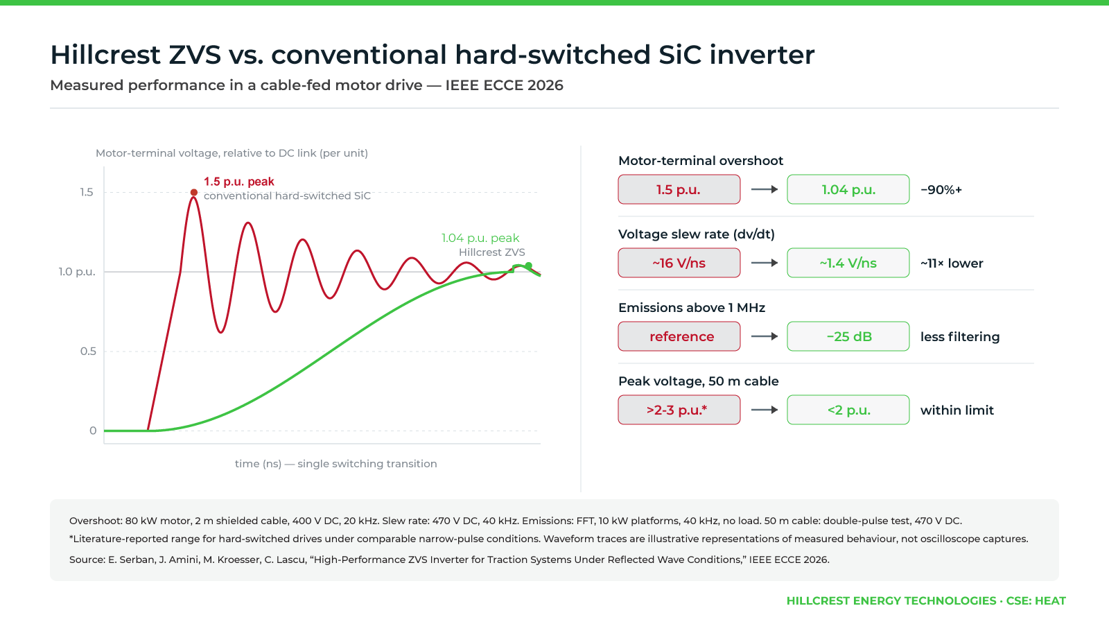
Hillcrest Energy Technologies has reported peer-reviewed test results showing that its zero-voltage-switching (ZVS) inverter technology reduced motor-terminal voltage overshoot by more than 90% compared with a conventional hard-switched silicon carbide (SiC) inverter.
The research, originating in electric vehicle (EV) traction applications, also demonstrated lower high-frequency electromagnetic interference (EMI). The findings are documented in a paper accepted for presentation at the IEEE Energy Conversion Congress and Expo (ECCE 2026) in Vancouver, Canada.
SiC power devices offer higher switching speeds and power density than conventional silicon devices, but rapid voltage transitions can create reflected-wave overvoltages between the inverter and motor. These voltage spikes can accelerate insulation aging and increase the risk of premature motor winding failure.
 Conventional approaches use passive filters to limit voltage overshoot, although these components can increase system size and introduce additional power losses.
Hillcrest’s ZVS technology addresses the issue during the switching event by transitioning devices when the voltage across them is near zero. This slows voltage transitions without relying on conventional snubber circuits that can increase switching losses.
In testing with an 80-kW motor connected through a two-meter shielded cable at 400 Vdc and a 20-kHz switching frequency, motor-terminal voltage overshoot fell from 1.5 to 1.04 times the dc-link voltage. This represents a reduction in the overshoot above the dc-link voltage from 50% to 4%.
Additional testing at 470 Vdc and 40 kHz showed that the voltage slew rate decreased from approximately 16 V/ns to 1.4 V/ns. High-frequency emissions above 5 MHz were approximately 25 dB lower than those of the conventional hard-switched SiC inverter.
The researchers also evaluated longer cable configurations. Under double-pulse testing with a 50-meter cable, the ZVS inverter maintained peak load voltage below twice the dc-link voltage.
According to Hillcrest, reducing voltage overshoot at the switching stage could help traction inverter designers manage motor insulation stress while reducing reliance on additional filtering hardware. The results also indicate potential benefits for EMI management in EV powertrains.
The research paper, High-Performance ZVS Inverter for Traction Systems Under Reflected Wave Conditions, was authored by researchers from Hillcrest Energy Technologies, Systematec GmbH, and Politehnica University of Timișoara.
“Controlling dv/dt at the switching event removes the cause instead of treating the symptom. Both theoretical analysis and experimental results demonstrate a significant reduction in EMI and motor-terminal overvoltage in cable-fed systems,” said Dr. Emanuel Serban, vice president of engineering at Hillcrest Energy Technologies.
Filed Under: Inverter, Power Electronics, Technology News