The rotor in an electric vehicle (EV) traction motor delivers torque through the motor shaft to the drivetrain. A rotor-position sensor, such as a resolver, reports the rotor angle needed for accurate torque control. If the sensor fails, fault-tolerant firmware can substitute a model-based estimate.
This article reviews how the inverter controller detects a failed resolver and switches to angle feedback from a software observer. It also explains when that fallback is no longer safe.
Sensing trouble
As shown in Figure 1, the traction inverter’s real-time controller receives rotor-position and current feedback from the motor drive. Field-oriented control (FOC) uses the electrical rotor angle to resolve current measurements into flux- and torque-producing components. An incorrect angle immediately corrupts both because the controller projects the measured current vector onto the wrong rotating reference frame.

Figure 1. Rotor-position and current sensors provide the feedback the inverter controller uses to regulate motor torque through the power stage. (Image: Allegro MicroSystems)
Importantly, a single anomalous reading is rarely enough for the controller to confirm a sensor fault. Instead, it compares the reported angle with a model-based estimate calculated from commanded voltage and measured phase currents without using the resolver output. If the resolver stalls or drifts, its output diverges from the estimate. The controller tracks that difference as a residual, giving the diagnostic firmware a measurable quantity to evaluate over successive control cycles.
After detection
When the residual is significant enough to suggest a fault, the controller takes the following steps:
- Confirm the fault. The residual must persist for a calibrated number of control cycles, preventing a noisy sample from triggering an unnecessary fallback.
- Isolate the source. Diagnostics determine whether the error originates in the resolver or elsewhere in its measurement path.
- Select the fallback. A qualified redundant sensor or model-based estimate replaces the failed signal.
- Derate operation. The controller limits torque to the range validated for the selected fallback and warns the driver that service is required.
Fallback is acceptable only while the controller can keep torque within validated limits. Otherwise, the inverter disables its gate drivers rather than act on an uncertain estimate. This action stops active switching and removes commanded motor torque.
If high-voltage isolation is also required, the contactors disconnect the battery, and active-discharge circuitry drains energy from the dc-link capacitor. Torque removal stops propulsion, while battery isolation and dc-link discharge de-energize the inverter’s high-voltage side.
How a virtual sensor takes over
A virtual sensor is a software observer that estimates rotor angle from the motor’s electrical behavior. As shown in Figure 2, a resolver encodes rotor angle in the changing amplitudes of its sine and cosine outputs. A connector fault disrupts this relationship, causing the reported angle to diverge from the observer’s estimate.
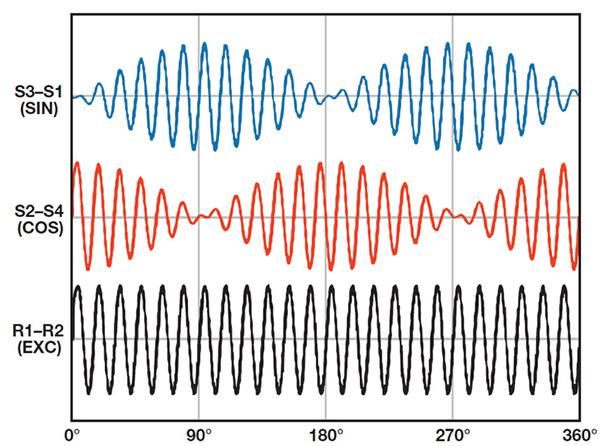
Figure 2. Resolver sine and cosine amplitudes vary over one shaft revolution while the excitation waveform remains constant. (Image: Analog Devices via DigiKey)
The inverter may then retain torque control by using the observer estimate for angle feedback. Based on a calibrated motor model, the observer derives angle and speed from the phase-current response to commanded voltage.
As shown in Figure 3, a fault flag transfers the control loop from measured to estimated feedback. Before the transfer, the controller aligns the observer with the last trusted sensor state. This alignment is crucial because an angle discontinuity would appear immediately as a torque step.

Figure 3. A fault flag switches the vector-control loop from sensor feedback to rotor-angle and speed estimates. (Image: MDPI)
Once the observer takes over, estimation uncertainty sets the operating limits. Back electromotive force (back-EMF) gives the observer reliable position information at sufficient motor speed. Its magnitude falls as the motor slows and approaches zero near standstill.
Notably, the weakening signal marks a physical operating boundary, not a calibration problem. A back-EMF observer can’t reliably estimate rotor position near standstill. If the estimate no longer supports safe torque control, the inverter removes motor torque as the driver brings the vehicle to a stop.
Continued operation still has its limits
Not every fault permits degraded operation, even temporarily. After a rotor-position signal fails, the controller can substitute a validated observer estimate if voltage and current feedback remain valid.
In contrast, losing a current-sensor channel is more serious because it weakens torque-control feedback and diagnostic coverage. Whether the inverter derates or stops depends less on what failed than on whether the remaining measurements provide enough information for safe torque control. Table 1 shows how the same decision applies to sensing and power-stage faults.

Table 1. Fault response depends on whether the remaining control and protection paths can keep the drive operating safely.
Following the ISO 26262 process, engineers assess how these faults could affect the vehicle. Hazard analysis then sets safety goals that address unintended torque and failure to remove torque when required. Limp-home operation is acceptable only while the surviving sensing and control paths keep torque within validated limits. Otherwise, shutdown is safer, even if it temporarily strands the driver.
Of course, even the correct response does little good if the controller can’t determine whether a fault is real. Set too tight, the detection threshold may mistake electrical noise for a fault. Set too loose, it may allow sensor drift to destabilize torque control before detection. That’s why engineers tune the threshold using data from normal operation and controlled fault-injection tests across the validated operating range.
Summary
Fault-tolerant control doesn’t mean an EV can keep driving after every sensor failure. If a resolver fails on the highway, the inverter may rely on a software estimate and continue at reduced power. As the vehicle slows, the electrical signal supporting that estimate fades. When the controller can no longer trust the result, the inverter cuts motor torque, and the driver brings the vehicle to a stop.
References
- Evaluating Functional Safety in Automotive Image Sensors, onsemi
- Fault Diagnosis Methods and Fault Tolerant Control Strategies for the Electric Vehicle Powertrains, MDPI
- Design Priorities in EV Traction Inverters, Texas Instruments
- Electrical Vehicle Fault Tolerant Motor Control, OpEva
- Fault Diagnosis and Fault-Tolerant Control in New Energy Vehicle Electronic Control Systems: A Comprehensive Study, AI Eco EV
- Review of Fault-Tolerant Control for Motor Inverter Failure with Operational Quality Considered, IEEE
- A Technical Review of Modern Traction Inverter Systems Used in EV Application, ScienceDirect
- Signal-Based Position Sensor Fault Diagnosis Applied to PMSM Drives for Fault-Tolerant Operation in Electric Vehicles, MDPI
- AI-Based Virtual Sensor for Rotor Position Estimation, MathWorks
Related EEworld content
- What Are the Types and Uses of Position and Angle Sensors in an EV?
- Part I: Rotor Position Sensing Challenges in EV Traction Inverters
- Part II: Why Inductive Sensing is Replacing Resolvers in EV Traction Inverters
- Compact Rotor-Position Sensor Supports EV Motor Applications
- How Does ISO 26262 (Road Vehicles – Functional Safety Standards) Apply to EVs?
Filed Under: FAQs, Featured Contributions, Sensors