
Sebastian Ahling, Ph.D., Staff Research & Development Engineer, Lumafield
X-ray computed tomography (CT) can reveal the internal structure of electric vehicle (EV) components without requiring disassembly. The technology gives engineers a way to examine how a component is built while preserving the relationships between the parts inside it.
In Part I of this interview, Sebastian Ahling, Ph.D., staff research and development engineer at Lumafield, explained how CT can help engineers inspect assembled EV components and decide where further testing may be needed.
That same visibility becomes more important as EV systems become more tightly integrated and operate at higher power levels. In Part II, Ahling shifts the discussion toward what internal layouts can reveal about engineering decisions and how CT should be used alongside other forms of validation.
Here’s what Ahling has to say…
What can the internal layout of a component reveal about the engineering priorities behind an EV design?
You can usually learn a lot, but I’d be careful about treating layout as proof of design intent.
Packaging density, component count, connector strategy, cooling architecture, mechanical reinforcement, and the amount of integration all give clues about what tradeoffs the engineering team made. A highly integrated assembly might prioritize size, weight, cost, or assembly time. A more modular design might make serviceability, reuse across vehicle platforms, or supplier flexibility easier.
A switch module can be a useful example. Internally, the electronics are relatively sparse and a number of functions are consolidated into one networked module. That suggests the complexity is being handled at a different level of the vehicle architecture rather than locally inside the switch module.
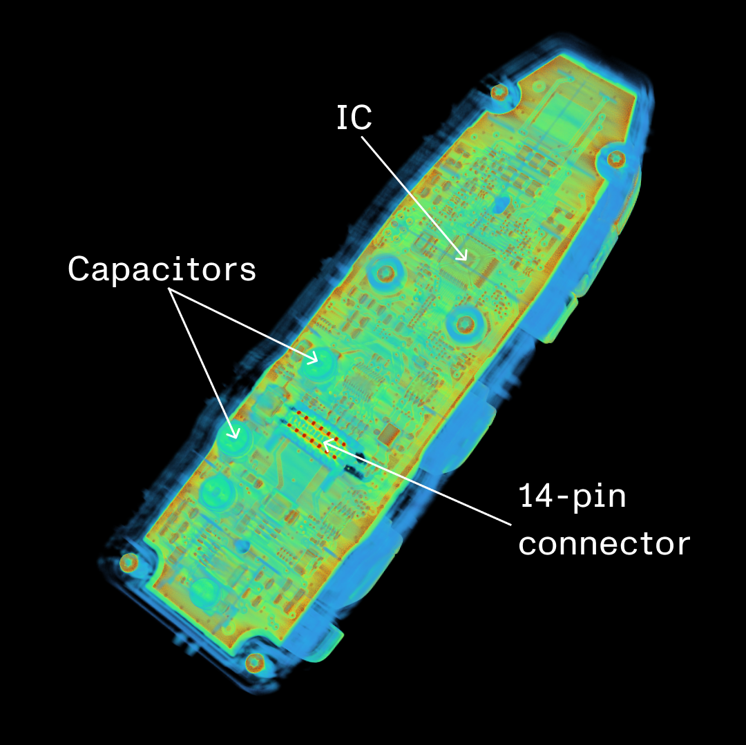
CT imaging exposes the internal electronics and connector layout of a vehicle switch module, allowing engineers to examine how functions are packaged within the assembly. (Image: Lumafield)
How should engineers interpret a component that looks relatively simple or conventional inside?
Simple isn’t the same thing as unsophisticated.
Sometimes a conventional architecture is exactly the right engineering choice. If a mature component or topology meets the electrical, mechanical, thermal, cost, and reliability requirements, there may be very little value in making it more complicated.
It can also tell you where the engineering effort went. In some of the components we’ve examined, several of the individual designs are fairly conventional. The interesting part is how functions are integrated across the vehicle and how those components fit into a vertically integrated manufacturing system.
For benchmarking, I’d avoid judging a design by complexity alone. I’d ask what problem the design solves, how efficiently it solves it, and what tradeoffs come with it.
What are the limits of imaging-based inspection, and when are electrical, thermal, or materials tests still needed?
CT gives you detailed 3D geometry and X-ray attenuation data. That means you can accurately measure internal features, clearances, wall thicknesses, voids, and other dimensions that may be difficult or impossible to access physically. You can also distinguish between materials to some degree when they have sufficiently different X-ray attenuation, although CT generally can’t tell you the exact chemical composition of a material.
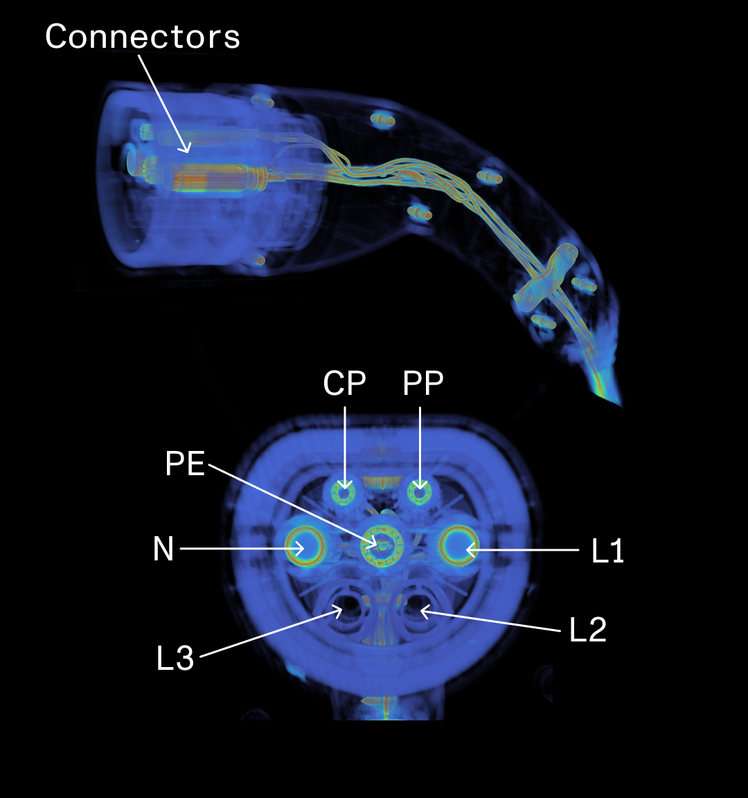
CT imaging can reveal connector geometry, internal conductors, and electrical interfaces within an assembled EV charging component. (Image: Lumafield)
However, there are practical limits. Resolution depends on part size, scan geometry, and the features you’re trying to resolve. Very dense or thick materials can obscure smaller features, and materials with similar attenuation can be difficult to separate.
CT also doesn’t directly tell you whether a circuit is functioning correctly, how a component behaves thermally under load, or how its materials will change over time. Those questions still require electrical, thermal, or materials testing. I see CT as providing the dimensional and spatial context around those tests. It can show what is happening internally, quantify it, and help engineers focus additional testing where it matters most.
How is EV component design changing as manufacturers move toward more integrated, higher-power architectures?
One clear trend is toward greater integration. Motors, inverters, transmissions, onboard charging, dc-dc conversion, thermal systems, and battery structures are increasingly being combined into larger functional assemblies. At the same time, higher-voltage architectures and faster charging are increasing power density and putting more pressure on thermal management, insulation, interconnects, and packaging.
That integration can reduce part count, weight, volume, and assembly complexity, but it also makes the remaining interfaces more critical. A thermal, mechanical, or electrical issue in one area of an integrated module can affect multiple functions.
From an inspection standpoint, that makes understanding the assembly in three dimensions increasingly important. Engineers are dealing with fewer isolated components and more tightly coupled systems, where packaging, thermal design, structural behavior, and electrical performance all interact.
Filed Under: Featured Contributions, Q&As, Test And Measurement