Electric motor selection often starts with datasheet ratings like peak power, torque, and speed range. These values are required for design, but they aren’t sufficient on their own. In an electrified or hybrid platform, the motor doesn’t operate in isolation. It’s one part of a coupled electromechanical system that also includes the inverter, energy storage, cooling, controls, and the driveline and vehicle structure around it.
A motor that looks ideal on a datasheet can underperform if:
- Its torque-speed curve doesn’t match the duty cycle
- It derates under thermal load
- It requires excessive gearing
- It introduces packaging and serviceability compromises
- The inverter is underpowered for the application
For engineers, motor selection is a system-level trade study, not a component-level procurement exercise.
Define the duty cycle first
The starting point is the load profile. Engineers need to know how much power the motor has to deliver, for how long, and how often transient events occur, along with how much energy it must deliver or recover over the operating cycle. That profile tells you what the motor is really being sized for, whether that’s short bursts such as launch assist and boost or sustained work such as traction and generation.
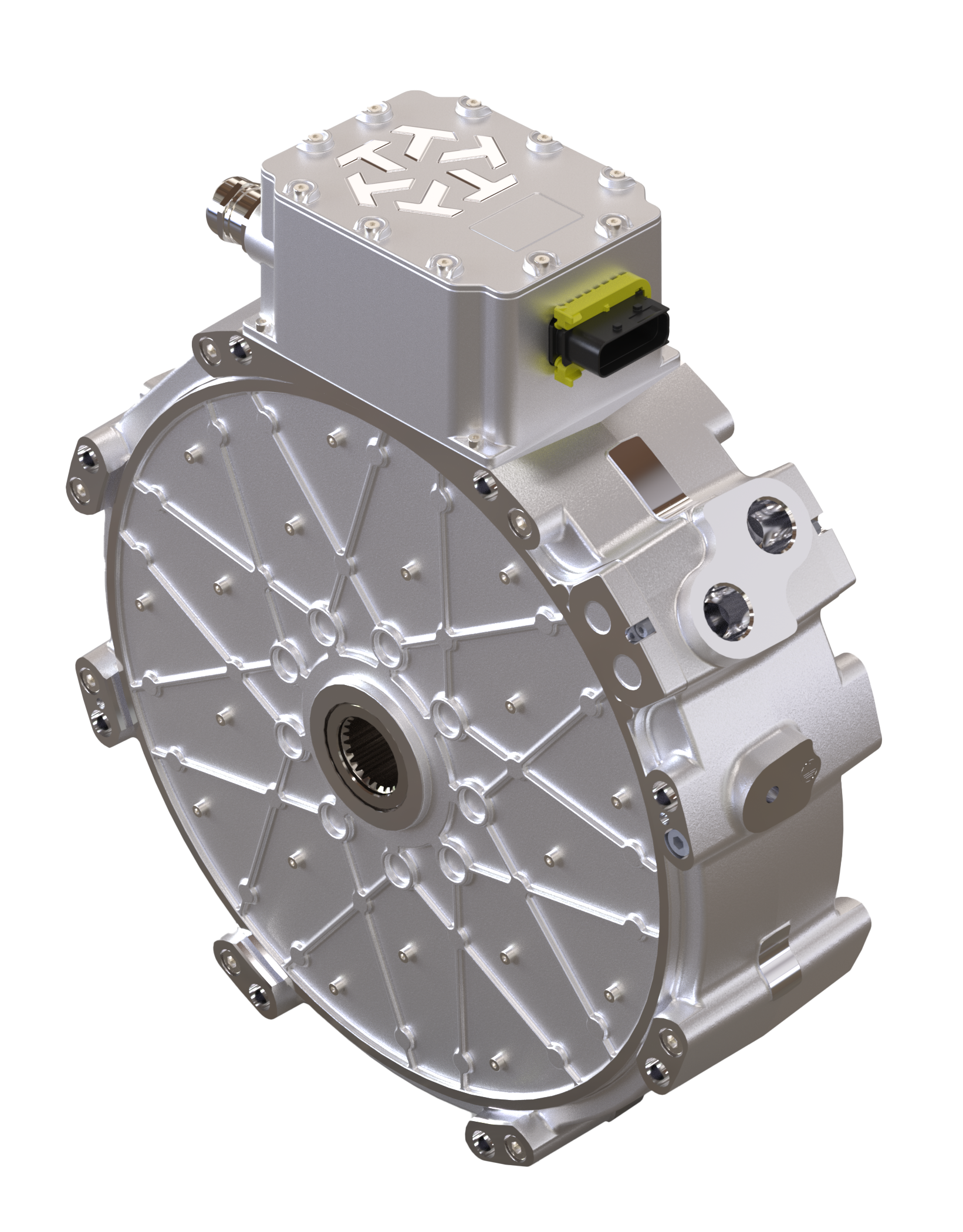
Figure 1. Axial flux motors can provide high torque density and a short axial length for space-constrained vehicle and equipment applications.
These distinctions are critical in hybrid architectures because the electric motor may not need to replace the primary power source. It may need to support the system only where electrification creates the most value:
- Filling torque gaps
- Reducing idle time
- Capturing braking energy
- Enabling zero-emission operation in defined zones
- Improving engine operating efficiency
Match torque output and quality to the application
Torque-speed alignment directly affects efficiency, gearing, controls, and packaging. Every motor has an efficiency map, and the best operating region depends on speed, torque, voltage, current, and temperature. If the motor’s most efficient operating region aligns with the mechanical load, the system can operate more efficiently and require fewer design compromises. If it isn’t aligned, the design may carry extra mass, incur more cost, and add control complexity.
Axial flux motors can offer advantages in vehicles and equipment where high torque density and short axial length are important. Their form factor helps engineers add electric torque within space-constrained drivelines or equipment envelopes. Topology isn’t the only consideration. Perhaps more important is whether the motor’s torque-speed characteristics reduce system complexity while meeting the required operating parameters.
Torque quality matters as much as torque quantity. Cogging torque and torque ripple affect:
- Smoothness
- Acoustic behavior
- Vibration
- Durability
These effects are particularly relevant at low speed, during transient operation, and in systems with long driveline paths or sensitive mechanical interfaces. In hybrid systems, motor torque ripple also interacts with combustion-engine pulsations and driveline compliance.
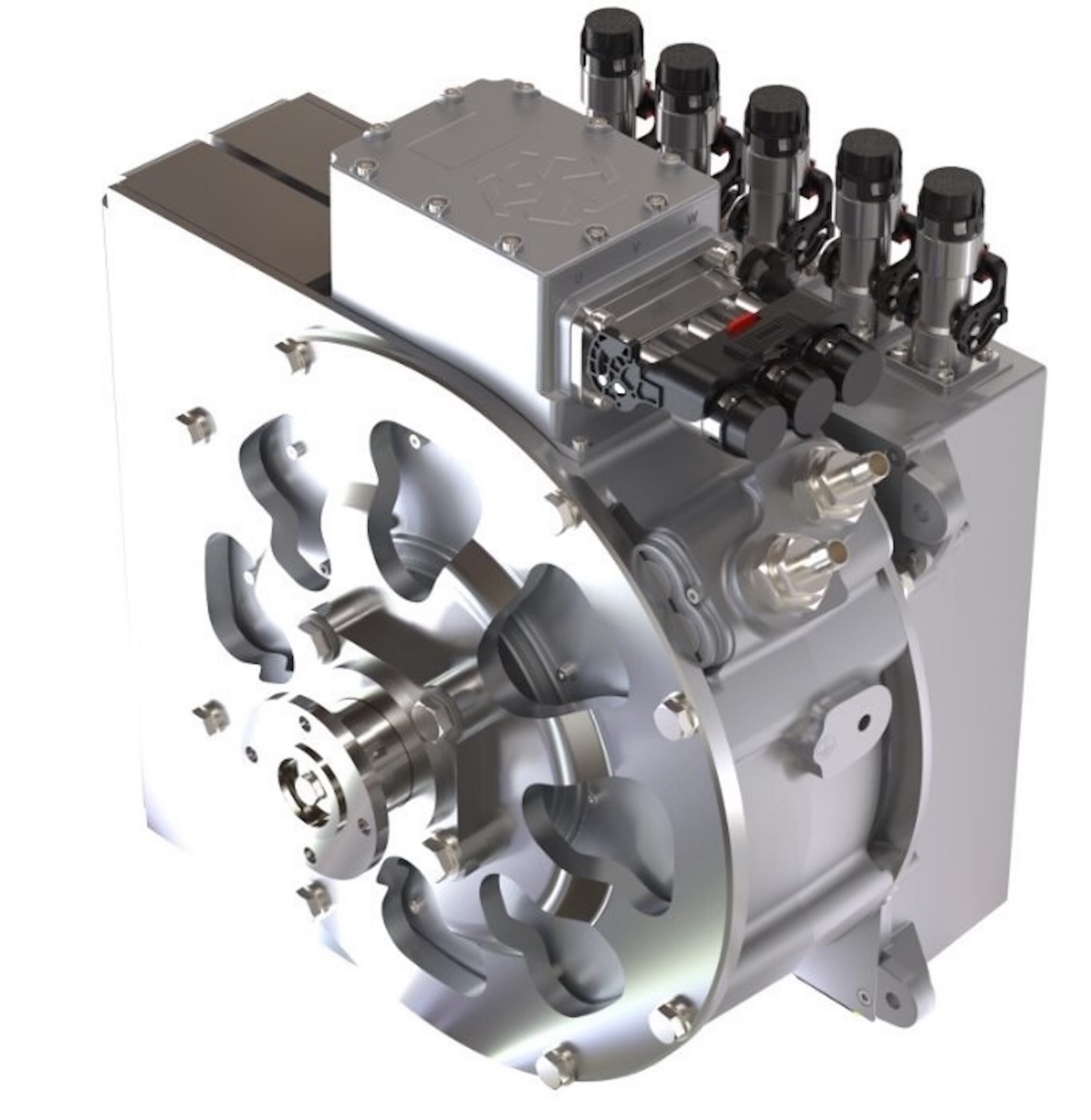
Figure 2. Axial flux motor shown as part of an electric power-take-off system paired with an inverter. Low cogging torque and torque ripple can reduce vibration and mechanical stress.
Torque quality is influenced by:
- Winding layout
- Slot and pole selection
- Electromagnetic design
- Inverter switching strategy
- Control algorithms
Low cogging torque and well-managed ripple reduce vibration and improve perceived refinement while lowering stress on shafts, splines, mounts, and couplers.
Design for sustained thermal performance
Peak output has limited value if the motor derates during normal operation. Thermal capacity determines continuous torque, service life, and reliability. High power density improves packaging. However, it also concentrates heat. The cooling system must be designed around the full duty cycle and not a single operating point.
Engineers should evaluate coolant selection, flow rate, pressure drop, heat exchanger capacity, pump sizing, routing, service access, and interaction with inverter cooling. In heavy-duty applications, several operating conditions can produce sustained thermal stress that isn’t captured by short-duration performance claims.
These include:
- Repeated starts
- Long grades
- High ambient temperatures
- High payloads
- Limited airflow
- Regenerative braking events
Pair the motor and inverter as a subsystem
The inverter determines how much of the motor’s capability is usable. Voltage range, current capacity, switching behavior, thermal limits, protection strategy, and software all influence real output. A motor with strong electromagnetic performance can still be constrained by an inverter that isn’t matched to the application.
Controls define:
- When to draw or recover energy
- How the system is calibrated for efficiency
- How to blend torque sources and adapt to dynamic load conditions
- How to protect the system under transient conditions
In hybrid rail, for example, control strategy may need to coordinate traction demand, onboard energy storage, charging windows, station approaches, infrastructure gaps, and state-of-charge targets.
Design for the platform, not the test bench
Packaging constraints often drive motor architecture decisions. Motors compete for space with batteries, inverters, cooling hardware, and other vehicle systems, while still needing room for maintenance access. Details like connector position, shaft configuration, and service clearance can determine whether a solution is practical.
Electric machines introduce rapid torque response, torque reversals, and regenerative loading into mechanical systems that may have been designed around different assumptions. Shafts, splines, bearings, and other driveline components should be assessed for peak loads, fatigue, torsional dynamics, and thermal cycling.
In diesel-hybrid systems, combustion firing pulses may interact with motor torque and driveline compliance. Designing the driveline to absorb and isolate these loads is essential to convert high motor torque density into reliable field performance.
Select for system fit
The ideal motor isn’t always the machine with the highest peak number. The motor must:
- Match the duty cycle
- Be efficient in the most-used operating regions
- Manage heat under real loads
- Pair cleanly with the inverter and controls
- Fit within the available space
- Protect the mechanical interfaces around it
As electrification expands across commercial vehicles, off-highway equipment, and marine systems, motor selection will continue to move from specification matching to system engineering. Engineers who treat motor selection as part of the complete powertrain will be better positioned to deliver systems that perform reliably in the real world. Axial flux motors are one option where high torque density is a key system requirement.
Filed Under: Electric Motor, FAQs