As electric vehicles (EVs) add more cameras, radar, and other high-bandwidth sensors, the amount of data moving through the vehicle continues to grow.

Daniel Shwartzberg, Director of Automotive Business Development, Valens Semiconductor
At the same time, those data links have to operate alongside high-voltage power electronics that can generate significant electromagnetic interference (EMI).
That creates challenges for signal integrity and vehicle wiring. Shielding and twisted-pair cabling can help protect high-speed links, but they also add weight, cost, and complexity, while emerging zonal and centralized architectures are increasing the need to move large amounts of data over longer distances.
Daniel Shwartzberg, director of automotive business development at Valens Semiconductor, works with OEMs and Tier-1 suppliers on high-speed automotive connectivity. In this interview, he explains how engineers can keep data links reliable in noisy EV environments and where conventional shielding approaches start to fall short.
Here’s what he has to say…
What makes high-speed data connectivity harder in an EV than in a conventional vehicle architecture?
Electric vehicles simply pack in a lot more electronics, and many of those systems run at high power. Traction inverters and other switching converters throw off a surprising amount of electromagnetic interference. That means high-speed data links have to stay robust in a much noisier electrical environment than you’d typically find in a traditional combustion-engine car.
How does inverter switching noise couple into nearby data lines?
A decent chunk of that noise radiates straight out of the switching circuits and high-voltage cables, and then gets picked up by nearby data harnesses. That happens even when those cables are shielded.
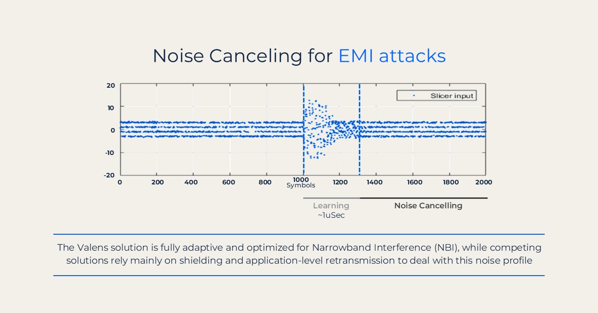
An adaptive noise-cancellation system responds to narrowband interference (NBI) affecting a high-speed data link. (Graphics courtesy of Valens Semiconductor)
The problem is that shielding doesn’t maintain the same performance forever. Temperature swings, constant vibration, and mechanical stress slowly degrade both the cable and its shield over the years. So, a link that looks fine in a clean lab still needs enough built-in margin to keep working reliably for the full life of the vehicle. Also, as sensor bandwidth continues to rise, this becomes more and more challenging.
How much does physical separation between high-voltage cabling and data harnesses help reduce interference?
It helps. The catch is that real vehicles don’t have unlimited space. With the high voltages and currents being switched around in an EV, a fair amount of EMI is inevitable, and the overall electrical architecture doesn’t always let you maintain the ideal separation. Distance is useful, but you can’t count on it as the only solution.
Where do shielding and twisted-pair cabling reach their practical limits in an EV harness?
Shielding and twisted-pair cabling are still essential tools, but they come with trade-offs. Thicker or denser shielding adds weight, bulk, stiffness, and cost, and the connectors and terminations often end up being the weak spots anyway. In the end, it’s smarter to design the data link itself, so it can tolerate a harsh electromagnetic environment rather than trying to solve every interference problem by piling on more metal around the cable.
How much aggregate bandwidth do current camera and radar systems generate?
It adds up fast! One OEM platform we work with runs seven ADAS cameras at roughly 4 Gbps each, so that’s already about 28 Gbps just from the cameras. Factor in radar, especially the newer imaging units or systems that send raw or lightly processed data toward central compute, and you’re easily looking at well over 30 Gbps in total. As vehicles add more sensors and higher-resolution imagers, that number will only keep climbing.
What kind of range penalty does harness mass represent in an EV?
There’s no single magic number. It depends on the vehicle, but every kilogram counts. Cutting back on copper, shielding, and overall harness complexity saves weight, eases packaging constraints, and ultimately helps the car’s efficiency and range.
What changes in wiring topology when a link moves to a single asymmetric long-reach connection?
It opens the door to cleaner zonal and centralized architectures. Instead of scattering compute around the vehicle and running dozens of individual point-to-point links, you can push high-bandwidth sensor data over longer asymmetric connections straight to a central or zonal computer. That simplifies the wiring, can reduce harness weight, and makes it much easier to build the high-speed backbone these newer electrical architectures need.
What does EMC validation look like for a high-speed data link before the full vehicle is available?
It’s a staged process. The silicon supplier starts at the component level, checking how the link holds up under electromagnetic stress. The Tier-1 then tests it inside the actual ECU or module. Only later does the OEM get to full-vehicle testing, where everything is running together. Doing the early work thoroughly cuts the risk of finding a connectivity problem only when you’ve already reached that very expensive stage of the program.
How do engineers determine the margin a high-speed EV data link needs to remain reliable as shielding and connectors degrade over time?
This depends upon many factors, but one of the key questions that needs to be addressed is how much electromagnetic noise the receiver of that link can withstand.
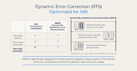
MIPI A-PHY uses dynamic local retransmission to correct errors caused by electromagnetic interference while maintaining bounded latency.
That’s a fundamental data point that helps form the basis of the additional analysis. The cables will age similarly irrespective of the link technology being deployed, so what’s crucial is to understand when that degradation may begin to impact the link. The lower the amount of noise that the receiver can withstand, the more margin may need to be built in.
In third-party testing carried out for global OEMs, MIPI A-PHY withstood approximately 20 dB more noise than legacy technologies, which could reduce the additional margin required.
Is the main benefit of reduced harness mass less copper and easier packaging, or can engineers quantify a meaningful impact on EV range?
If you can deploy extremely high bandwidth links that have enough throughput to allow for the convergence of multiple links into a single cable, this can have a meaningful impact on the mass, complexity, and cost of the harness. Less copper, fewer connectors, and smaller ECUs can all contribute to reduced vehicle weight.
When we then factor in the emerging zonal and centralized E/E architectures that the industry is now employing, and the streamlined systems that are resulting, these weight savings have the potential to continue to scale. Now, I’m not an EV battery system engineer, so I can’t directly translate the weight savings into additional range, but vehicle engineers will be better positioned to quantify the impact in the context of a specific vehicle design.
Filed Under: Featured Contributions, Q&As